As the CO2 storage industry increasingly handles third-party supplies of CO2, the landscape is set to change as the industry looks to exploit conveniently located sites. By Royal Bank of Canada analysts, London.
Permanent CO2 storage relies on depleted oil and natural gas reservoirs or saline aquifers. Depleted reservoirs are extensively mapped and well understood given extensive geological information from decades of drilling. Depleted oil and gas reservoirs are known to be safe, having trapped hydrocarbons over long periods of time. Saline aquifers, while safe and effective, have comparatively limited data and are generally more expensive given their lower storage efficiency.
Today, there are only a handful of dedicated CO2 storage sites and all are located immediately adjacent to the CO2 source, foremost among which are gas-processing plants at CO2-rich gas fields including Sleipner, Snohvit, and Gorgon. As the CO2 storage industry increasingly handles third-party supplies of CO2, the landscape is set to change as the industry looks to exploit conveniently located sites.
The geology of most regions has been mapped extensively and the global distribution of porous reservoirs and impermeable seals is well established, and storage sites, ie traps, within complexes that encompass the wider geology including overlying secondary seals can be readily identified.
Audited capacity
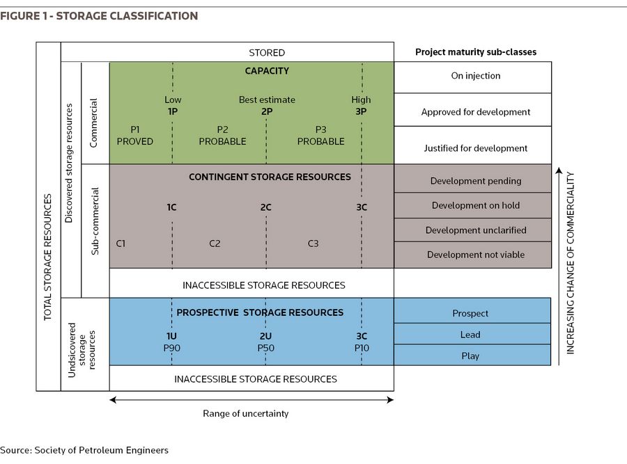
Storage sites have a defined capacity. The CO2 Storage Resources Management System (SRMS) provides estimates of storable quantities in a similar manner to the Petroleum Resource Management System (PRMS) categorises reserves: Stored; Proved, Probable and Possible Capacity; and 1C-3C Contingent Storage Resources plus Prospective Storage Resources.
A key driver is storage efficiency, which denotes the pore space that can be filled with CO2. Efficiencies range from 2%–5% in open aquifers to over 70% in depleted gas fields. The interaction of storage efficiency and facility injectivity frame a storage site and affect its development costs. Reservoirs with high storage efficiency – such as a depleted gas field – entail a smaller footprint, which should limit the number of required wells and therefore development costs. In contrast, a large open aquifer with low storage efficiency may require a string of injection hubs, requiring additional infrastructure and monitoring facilities.
The storage industry draws heavily on the expertise inherent in the oil and gas industry; specifically a knowledge of a complex’s faults, pressure regimes and potential limitations. Although CO2 injection into a substantial, regional, aquifer might generate only a small increase in reservoir pressure – as demonstrated at the Sleipner field in Norway – other sites might require additional "reservoir management" to mitigate seal fracture risk; for example at Chevron’s Gorgon field in Australia formation water is extracted via water production wells to make room for the injected gas.
CO2 is injected into a reservoir in a supercritical state achieved by compressing (and heating) the gas to the point at which it has the density of a liquid and assumes its minimum volume to maximise storage capacity. Assuming an average geothermal gradient (25°–30°C/km), the minimum depth for CO2 injection in supercritical state is approximately 800m (2,625ft). The utilisation of depleted oil and gas fields comes with inherent benefits and risks:
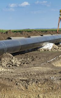
* Access to existing infrastructure – Existing compression facilities and injection wells is the obvious boon, and having previously stored oil and/or gas, the structure is known to have the necessary combination of reservoir, seal and trap.
* Operator knowledge – The field operator has a good knowledge of reservoir performance, and in a depleted state some of the risks associated with gas injection and fracturing are reduced.
* CO2 cooling – CO2 cools drastically during expansion, presenting the risk of dry ice forming within pipelines and valves; consequently, CO2 delivered for storage in low pressure/depleted reservoirs might initially need to be shipped as a gas to simplify the injection process. However, we would note that it is unusual for production wells to be viable CO2 injectors, due to their up-dip locations and construction (grade of steel).
* Leakage risk – Legacy wells are a key leakage risk – well bore integrity has to be accurately assessed; given these concerns, some of the largest and oldest fields might be ruled out as storage sites.
At the depleted Goldeneye gas field, which was earmarked previously as a storage site, the reservoir pressure at the start of injection was expected to be less than 70% of hydrostatic and to remain substantially below ambient pressure for the duration of the injection operation. In contrast, at fields that have benefited from secondary recovery techniques, the produced hydrocarbons are often replaced with injected water to help maintain reservoir pressure for CO2 injection, this process would need to be reversed.
Despite legacy fields presenting potential challenges, the ERVIA project in Ireland and the Hynet project in the UK have earmarked existing production facilities – at Kinsale Head and Morecambe Bay, respectively – for re-use. In the Netherlands, the Porthos and Athos projects are assessing the potential of a number of offshore fields.
In areas with existing onshore and near-shore gas facilities, we could envisage the potential for competition between CO2 sequestration and seasonal green hydrogen storage capacity. However, salt caverns continue to be the preferred storage site for H2.
The storage industry draws heavily on the expertise inherent in the oil and gas industry. Utilising depleted oil and gas fields provides access to existing infrastructure, compression facilities, and injection wells. Thereafter, we see the potential for attention to focus on compact reservoirs with existing infrastructure, as the cyclical nature of hydrogen injection/production may lend itself to the re-use of existing gas facilities.
Combined with society’s concerns about subsurface injection, hydraulic fracturing and seismic activity, most storage sites in Europe are likely to be located offshore. This also helps address the issue of ownership – as with oil and gas exploration, national and regional laws control access and regulate activities, and long-term responsibility. Where the subsurface is owned by the government, it is likely that the government would take long-term responsibility for a site’s performance. For example, offshore Norway, all obligations are transferred to the state in accordance with the regulations relating to the exploitation of subsea reservoirs.
It is worth noting that CO2 storage activities have been undertaken onshore in Europe. In 2006-13 TotalEnergies injected CO2 at its depleted Rousse field in the Aquitaine Basin in south-west France and at Ketzin in Germany there was a test site injecting CO2 into an aquifer in 2008–13. In North Africa, BP’s intensely monitored In Salah CCS project was operational in 2004–11.
Storage risk
The greatest risks associated with a storage operation stem from the initial drilling and completion activities, specifically in depleted fields with remnant hydrocarbons, and CO2 injection activities. Technical risk increases with reservoir pressure and commercial risk increases with stored volume: the owner is liable for leakage/emissions.
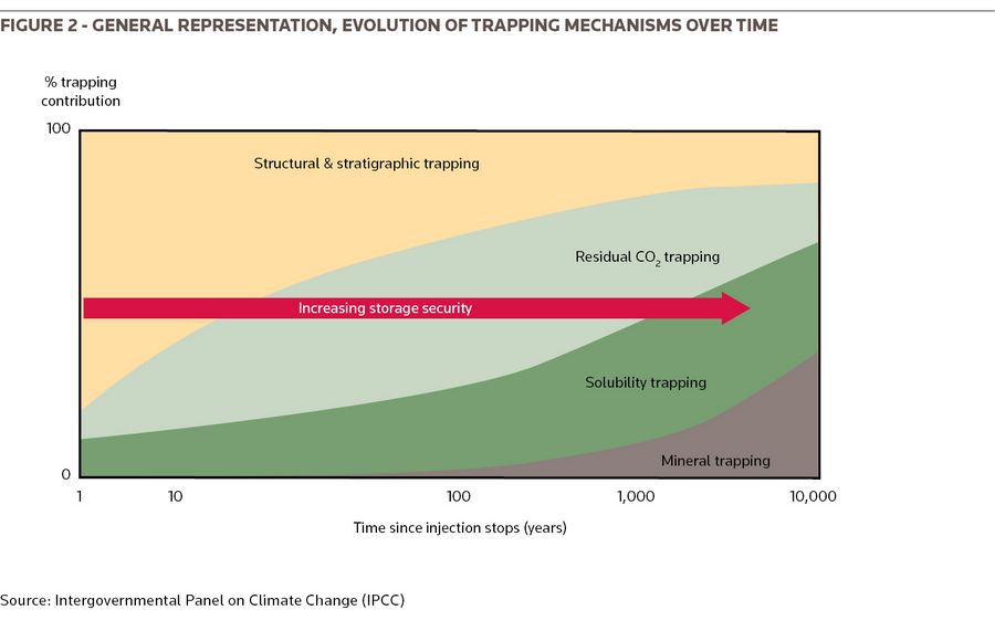
The plugging and abandonment of development wells is another operational risk; but, as with producing fields, the plan should be to complete the development with as few wells as possible. CO2 injection wells are located away from the crest of the structure, based upon the assumption that the CO2 would migrate up-dip away from the well. Thereafter, storage risks are believed to be minimal and decrease over time, as CO2 is absorbed into the brine in the reservoir (see Figure 2).
Structural geological and rock mechanical aspects of the storage system are most critical in the early injection phase, when attention needs to be focused on the build-up in reservoir pressure. Lessons have been learned at the heavily monitored, onshore, In Sahal facility and offshore at Snohvit, where the operator switched to a secondary reservoir and drilled an additional injection well. CO2 injection can stimulate natural fractures, but while they may propagate upwards into the lower cap rock they are unlikely to extend through overlying seals. Moreover, fractures tend to reseal as a result of shale creep, after injection activities cease. In depleted gas fields, the initial CO2 deliveries are likely to be into a depressurised reservoir and the final reservoir pressure is likely to remain below the virgin pressure of the oil and gas reservoir.
Storage monitoring
Tracking the distribution of the CO2 plume is important, its development is not always homogeneous and it cannot be allowed to extend to potential conduits to the surface, such as significant faults, fracture zones and abandoned wells, nor to any nearby producing oil and gas wells.
Monitoring, measuring and verification (MMV) is a key element of any development. Depending upon the location (onshore versus offshore) and the available infrastructure (number of wells) storage performance can be monitored using a portfolio of geophysical and geochemical methods, including 4D time-lapse seismic, micro-seismic, wellhead sampling including tracers, down-hole logging, core analysis, surface gas monitoring, groundwater aquifer monitoring and satellite data. To-date, there has been no leakage to surface from storage sites or blowouts of modern injection wells; however, CO2 storage activities at In Salah were suspended in mid-2011 following a risk assessment.
Studies suggest that it is very unlikely that large volumes of CO2 would find pathways from the storage reservoir at depths of 1,000–3,000 meters to the seafloor 1. More generally, it is worth noting that verification is important, as the site owner is paid for the gas it stores – “No Sequestration without Verification” – consequently injection and any leakage need to be measured.
Costs and ownership
The primary costs associated with storage include injection, monitoring, and decommissioning:
* Injection – New injection wells may need to be drilled, though existing injector wells for secondary recovery in depleted oil and gas fields may be repurposed. It is also likely that these fields would have pre-built pipeline and compression capacity on site. Injection wells can be costly, higher end for offshore sites, with the required number of injectors depending on the storage efficiency of the reservoir.
* Monitoring – Monitoring is likely to be required on a long-term basis, potentially spanning decades after decommissioning.
* Decommissioning – Operators of storage sites will be required to decommission all well sites and above ground facilities and infrastructure.
The long-term ownership, and the associated liabilities, represent a key sticking point for the industry. As an example, following the closure of a CO2 site in Norway, all obligations revert to the government. However, the operator would need to demonstrate to the regulator that the storage facility performed as anticipated, reservoir models and continuous monitoring are key requirements; no leakage has occurred and reservoir conditions are stable; the facility has been decommissioned; thereafter there is a minimum surveillance period of at least 20 years. Up until the handover, the operator would have had to provide some financial security.
Footnote
1 - Zero Emissions Platform, ZEP-report-CO2-Storage-Safety-in-the-North-Sea-Nov-2019.pdf
To see the digital version of this report, please click here
To purchase printed copies or a PDF of this report, please email gloria.balbastro@lseg.com